2025/02/19
The key to signal selection is to use a radio frequency filter, whose function is to allow the signals of the desired frequency to pass through while blocking the rest. The working principle of the filter is to generate resonance at a specific frequency. It can be compared to a swing on the playground. To make the swing go higher, you must synchronize the time of pushing with the frequency of the pendulum’s swing and resonate with the frequency of the swing. Similarly, a correctly designed resonant circuit will allow signals of the correct frequency to pass through while suppressing other frequencies. A quantitative measure of the semaphore that is allowed to pass, as opposed to suppressing unwanted frequencies, is called the filter quality (or Q) factor. We hope the Q factor is as high as possible. In fact, a filter is not sufficient to allow a single frequency to pass. Signals will pass through a certain frequency range, which is called the filter’s bandwidth. The bandwidth requirements will narrow or widen according to the wireless standard served by the filter. Significantly, it should also be noted that the size of the filter is proportional to the wavelength of the signal at resonance in the cellular technology. The most widely used filter in cellular technology is the acoustic filter, mainly because they are small in size and have a high Q factor. The acoustic filter is built on a special substrate called a piezoelectric substrate (usually lithium tantalate, LiTaO3), which converts mechanical stress into electrical energy and vice versa. They are very compact because of the acoustic resonance phenomenon at gigahertz frequencies, of which the wavelength is within the micrometer range, while the wavelength of the filter based on electromagnetic resonance is within the centimeter range. Given this, the RF acoustic filter industry has experienced a huge boom in the past decade with the rise of mobile communications, and size is its main driving factor in this article, in which we will study various RF filter technologies, including new developments in future wireless communication:
Surface acoustic wave has the temperature compensation; bulk acoustic wave (FBAR, SMR, CMR, XMR); LC filter (LTCC, IPD); new filters for the wireless future.
I. Surface Acoustic Wave (SAW) Filters
Initially, the maximum operating frequencies of 1G, 2G and 3G mobile phones were approximately 2 GHz. The 2G GSM band was 900 MHz, the PCS band was 1900 MHz, and the 3G phone’s Band 1 was 2100 MHz, while Band 5 was 850 MHz. SAW filters can achieve a quality factor of around 800 at these frequencies, which is sufficient for mobile communications. SAW filters are implemented on piezoelectric substrates, which have aluminum strips on them. The aluminum strips have a comb-like structure, called interdigital transducers (IDT), which can convert electrical signals into mechanical vibrations, also known as acoustic waves. These waves propagate laterally along the surface of the piezoelectric substrate and collide with other IDTs placed at strategic distances on both sides and rebound back. According to the physical structure of this configuration, SAW filters have specific resonant frequencies.
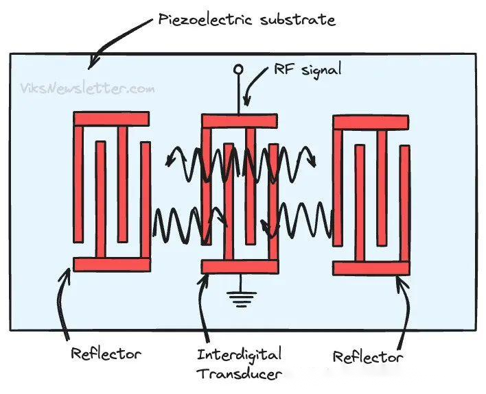
Surface Acoustic Wave (SAW) Resonator
As the working frequencies and bandwidths of subsequent wireless standards keep growing, it becomes increasingly difficult to fabricate SAW filters with narrow aluminum feature sizes on piezoelectric substrates and achieve a filter bandwidth exceeding 100 MHz. Another issue is that the filter performance will change with temperature variations, which can be caused by external environmental factors or internal heat dissipation within the filter. To overcome these problems, improvements in SAW filter technology are necessary. These improvements have adopted various techniques, which we will see in the following text.
II. Temperature Compensation (TC) SAW Filter
The negative temperature coefficient of the piezoelectric substrate is approximately -20 ppm/C to -40 ppm/C, which means that as the temperature rises, the frequency response shifts to a lower frequency. TC-SAW filters overcome the temperature drift problem by using one of the following two techniques:
1. A thin layer of silicon dioxide (SiO2) is deposited on the top of the IDT structure. The positive temperature coefficient of SiO2 compensates for the negative response of the piezoelectric substrate, effectively achieving a frequency offset close to 0 ppm/C. However, this will lead to additional filter loss and spurious resonant modes.
2. Bond the piezoelectric substrate with another substrate with a lower coefficient of thermal expansion (such as sapphire or silicon dioxide). But this method has less temperature stability than the previous one.
Temperature stability is a necessary characteristic of the 4G LTE standard. Band 40 (2.3 – 2.4 GHz) almost coincides with the lower limit of WiFi (2.401 – 2.483 GHz), and this fact imposes strict requirements on the filter accuracy. However, as the wireless standard frequency becomes higher and higher, the width of the aluminum electrodes in the IDT becomes smaller, and SAW filters soon encounter problems of increased loss and electromigration at high transmission power. Although researchers have tried various metal alloys to alleviate this problem, it is the time to adopt new technologies currently.
III. Bulk Acoustic Wave (BAW) Filters
BAW filters address the issues of extending to higher frequencies and handling higher power requirements. There are two methods to create acoustic wave filters that utilize the resonant phenomenon of bulk piezoelectric materials:
1. Thin Film Bulk Acoustic Resonator (FBAR)
2. Surface Mount Resonator (SMR)
IV. Thin Film Acoustic Wave Resonator (FBAR)
The working principle of FBAR is straightforward and easy to understand. It consists of piezoelectric materials sandwiched between the top and bottom electrodes. When an alternating voltage is applied to the electrodes, due to the reverse piezoelectric effect, mechanical strain is generated in the substrate. This results in acoustic waves reflecting back and forth between the two electrodes, thereby forming a resonator. Then, a BAW filter is fabricated by coupling the resonators together.
The “thin film” in FBAR refers to the electrodes and piezoelectric substrate implemented in a suspended form on a supporting substrate. The supporting substrate is selectively etched below the piezoelectric material to enable free vibration (and resonance) of the substrate. The high acoustic impedance interface between the bottom electrode and the air allows the acoustic waves to reflect back to the piezoelectric material, forming the resonator.
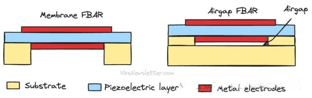
Film-based Bulk Acoustic Resonator (FBAR)
Based on this working principle and using aluminum nitride (AlN) as the piezoelectric material, a Q factor greater than 2000 can be achieved within the 2-8 GHz range, making it an ideal choice for 4G LTE/5G applications. FBAR can adapt to temperature changes and is compatible with CMOS foundry processes. This makes the commercialization of FBAR technology attractiv whi.e many large enterprises such as Broadcom, Qorvo, STmicroelectronics, Samsung, TDK (Qualcomm), and TAIYO YUDEN, join this field.
The method to increase the operating frequency of FBAR filters is to thin the AlN substrate. For example, by reducing it to 120nm, FBAR can operate at 24 GHz. Another method to achieve high-frequency operation is to use higher-order resonant modes and overmodulated BAW (OBAR) resonators.
The disadvantage of BAW filters is difficult to manufacture filters with large bandwidths. The bandwidth largely depends on the characteristics of the piezoelectric material. To increase the bandwidth, researchers have successfully doped scandium into AlN, thereby increasing the bandwidth by more than twice. Strong piezoelectric materials such as lithium niobate (LiNbO3 or LN) have also shown good results.
V. Fixed Resonator (SMR)
The essence of FBAR lies in the presence of a high impedance between the electrode and the air interface, allowing sound waves to be reflected back to the resonator. The same effect can be achieved by placing a so-called acoustic Bragg reflector beneath the piezoelectric material with top and bottom electrodes.
The acoustic Bragg reflector consists of a series of alternating high and low impedance layers (such as tungsten and silicon dioxide), so each interface part of the signal is reflected back. The more layers in the Bragg reflector, the higher the impedance presented by the reflector due to multiple reflections. By placing the Bragg reflector beneath the bottom electrode of the BAW resonator, the signal is reflected back into the piezoelectric material, thereby causing resonance.
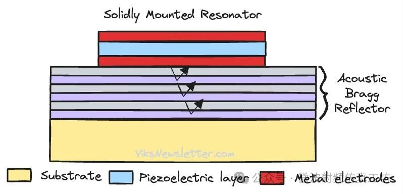
Fixed-mode resonators (SMR)
The SMR BAW filter has outstanding performance. For instance, Qorvo reported an SMR filter that can handle 5W of RF power with a peak of 40W. Recently, they also reported a new type of SMR BAW filter, which uses scandium doping and supports operation in the 1-8 GHz range, covering the 5G and Wi-Fi 6E frequency bands.
VI. Profile mode resonators (CMR) and XMR
For FBAR and SMR BAW filters, only one resonance can be achieved based on their physical structure, which means that different filter chips are required for each working frequency band. With the rapid increase in cellular frequency bands, it is necessary to implement multiple working frequency bands on a single BAW chip. The profile mode resonator (CMR) BAW technology is developed for multi-band operation.
The physical structure of the CMR BAW resonator is a mixture of the IDT structure used in SAW filters and the bottom electrode used in BAW filters. As a result, multiple resonant modes can be excited in both the lateral (along the surface, such as SAW) and longitudinal (such as BAW) directions, realizing simultaneous resonant modes at different frequencies. This enables the design of multi-band BAW resonators that can handle multiple frequency bands simultaneously.
In FBAR, SMR, and CMR, achieving a wide filter bandwidth has always been a problem due to the limited coupling coefficient. To increase the coupling degree and thereby increase the filter bandwidth, researchers have discovered methods to combine multiple operating modes. Instead of purely designing the metal shape of the resonator from an overview perspective, researchers design the resonator by looking at its cross-section and related modes. Through complex design of the BAW filter electrodes, a new type of BAW filter called XMR has been developed for wide bandwidth. Such filters are very new, still under research and development.
VII. Integrated-element filters
As we enter the 5G New Radio (NR) era, the bandwidth of the n77-n79 frequency bands is ten times larger than that of previous generations. Due to the relatively low coupling through piezoelectric materials, SAW and BAW technologies have always had the problem of excessive bandwidth. To solve this problem, today’s 5G smartphones generally use integrated-element LC filters. Inductors (L) and capacitors (C) are implemented on multi-layer substrates, such as low-temperature co-fired ceramics (LTCC) or integrated passive devices (IPD). The Q values of such passive devices on the substrate are not high. Therefore, these filters do not have good selectivity. This can still be tolerated for two reasons:
1. The occupation of 5G frequency bands is still not as dense as that of previous generations, so the lower selectivity of the filter may be acceptable.
2. The wide filter bandwidth required by 5G can be achieved. Since SAW/BAW do not perform well in this use case, there is no other option.
The main disadvantage of making filters of LTCC is that implementing passive elements using a multi-layer method results in an overall thickness that is too large and is not suitable for thin modern smartphones. Moreover, the low tolerance in the manufacturing process cannot bring about good yield rates.
IPD is a more advanced technology, especially when implemented on glass substrates. The manufacturing tolerance is stricter, the thickness is smaller, and high-density metal-insulator-metal (MIM) capacitors can be achieved, thereby enabling more compact and more strictly controlled filters. If GaAs IPD is used, it is possible to integrate the filter with the active circuit. However, with the rise of WiFi 7 and 6G cellular technologies, the limited Q value and poor selectivity will become problems in the future. More complex filters will be needed in the future.
VIII. Outlook for the Future
There are still many innovative methods to be studied and explored in RF filter technology’s future. We are still far from achieving all the goals. Nevertheless, here are some exciting advancements. Ultra-high Performance (IHP) SAW: Murata demonstrated an SAW filter with a Q value exceeding 4000 (more than 4 times higher than ordinary SAW) and operating frequency over 5 GHz. Various combinations of supporting substrates and piezoelectric materials are currently being studied to break through performance limits.
XBAR: Resonant Inc. was acquired by Murata in 2022, who has proprietary XBAR technology (a unique combination of SAW and FBAR BAW technologies) and is expected to provide acoustic filters for 5G NR applications (including the n79 frequency band).
XBAW: Akoustis is another company that promises to provide high-performance broadband acoustic filters for 5G and modern WiFi technologies. They develop their proprietary technology using single-crystal AlN films with better piezoelectric properties than polycrystalline AlN films.
Hybrid: Future RF filters may adopt a combination of carefully designed acoustic filters and LC filters to achieve a win-win effect. Published research indicates that the bandwidth is 900 MHz (3.3 – 4.2 GHz), and at 4.4 GHz (band n79), it provides 36 dB of suppression, with only a 200 MHz difference, which definitely has a bright prospect.
发表回复